Edexcel IGCSE Physics revision

Edexcel IGCSE Physics Electromagnetic induction questions

Revise the syllabus content for Electromagnetic induction, learn how to approach common exam questions, and study two worked examples with clear diagrams.

Edexcel IGCSE Physics Subtopic 6.d

Electromagnetic induction syllabus

Questions on electromagnetic induction can test recall, calculations, explanations, diagrams, data handling and practical skills. You should be able to:

  • 6.15 know that a voltage is induced in a conductor or a coil when it moves through a magnetic field or when a magnetic field changes through it and describe the factors that affect the size of the induced voltage
  • 6.16 describe the generation of electricity by the rotation of a magnet within a coil of wire and of a coil of wire within a magnetic field, and describe the factors that affect the size of the induced voltage
  • 6.17P describe the structure of a transformer and understand that a transformer changes the size of an alternating voltage by having different numbers of turns on the input and output sides
  • 6.18P explain the use of step-up and step-down transformers in the large-scale generation and transmission of electrical energy
  • 6.19P know and use the relationship between input (primary) and output (secondary) voltages and the turns ratio for a transformer: input (primary) voltage / output (secondary) voltage = primary turns / secondary turns
  • 6.20P know and use the relationship: input power = output power VpIp = VsIs for 100% efficiency

How to answer electromagnetic induction questions

  1. Add arrows to field lines and distinguish magnetic field direction from force direction.
  2. State what changes in the field or conductor before explaining an induced voltage.
  3. Apply the left-hand rule systematically and describe how reversing current or field reverses force.
  4. For transformer calculations, label primary and secondary quantities before using the turns ratio.

Electromagnetic induction example questions and worked answers

These examples show how information in a diagram, graph or experimental context becomes part of a complete exam answer.

Example 1: Reading an Experimental Diagram

Question 1

The student has a bicycle with a dynamo (generator) that supplies electricity for its lights.
The diagram shows the dynamo.
The friction wheel, W, presses against the bicycle tyre. When the student pedals, the friction wheel turns and causes part Y to rotate.
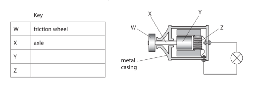
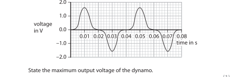
Cross-section diagram of a bicycle dynamo with labelled parts W (friction wheel), X (axle), and parts Y and Z to be named; shows metal casing and an electrical circuit to a lamp. The graph shows how the output voltage of the dynamo varies with time as the student pedals steadily.
State the maximum output voltage of the dynamo. Voltage-time graph for the dynamo output showing an alternating waveform over 0 to 0.08 s with peaks and troughs around ±2.0 V.
maximum output voltage = V

Final answer

Maximum output voltage = 1.6 V

Mark scheme points

  1. M1 1.6 V, or a voltage of magnitude 1.6 V.

Explanation

Maximum voltage is the greatest vertical value reached by the graph above zero. The positive peak is +1.6 V, so the maximum output voltage is 1.6 V.

Common mistakes

  • Do not give the peak-to-peak voltage; this would be the difference between the highest and lowest points.
  • Do not use the time axis to find the voltage.
  • Remember that the maximum output voltage is the positive peak, not the negative trough.
Example 2: Reading an Experimental Diagram

Question 2

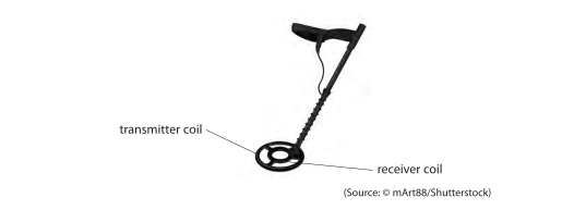
A device called a metal detector can be used to find metal buried underground. Photo of a handheld metal detector showing a circular coil end; labels indicate transmitter coil and receiver coil. Diagram 1 also shows the circuit for the transmitter coil with a cell supplying electronics connected to the transmitter coil.
The metal detector has two circuits, each containing a coil of copper wire.
Diagram 1 shows the circuit for the transmitter coil.
QUESTION 12 CONTINUES ON NEXT PAGE
The cell supplies direct current (d.c.). The electronics in diagram 1 change the direct current into alternating current (a.c.) in the coil. Alternating current is supplied to the transmitter coil.
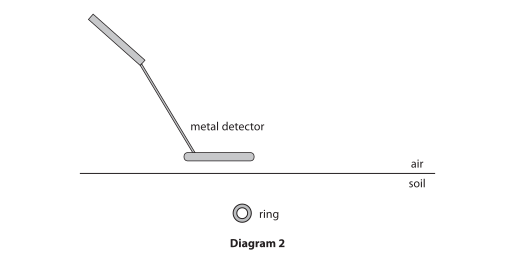
Diagram 2 shows a gold ring in the soil below the metal detector. Diagram 2: metal detector above ground surface with air above and soil below; a ring is shown buried in the soil beneath the detector.
Explain why there is an alternating current in the gold ring.

Final answer

The alternating current in the transmitter coil produces a changing magnetic field. This changing field cuts the gold ring, so a voltage is induced in the ring. The induced voltage drives an alternating current around the conducting ring.

Mark scheme points

  1. M1 The alternating current produces a changing magnetic field from the transmitter coil.
  2. M2 The changing magnetic field cuts the field lines through the gold ring.
  3. M3 A voltage is induced in the gold ring, causing an alternating current.

Explanation

The alternating current continually changes direction and size, so the magnetic field produced by the transmitter coil also changes. This changing field passes through, or effectively cuts, the conducting gold ring. Electromagnetic induction produces a voltage in the ring. As the magnetic field changes repeatedly, the induced voltage reverses repeatedly and drives an alternating current.

Common mistakes

  • State that the magnetic field is changing; a static field is not enough.
  • Use “cuts field lines” or “field moves through the ring”, rather than only saying that the ring interacts with the field.
  • Mention the induced voltage before stating that it produces the current.
  • Examiners reported that induced current instead of induced voltage was a main reason marks were missed, while “interacting” did not score.

Practise Electromagnetic induction questions

Build a focused practice set from this part of the Edexcel IGCSE Physics syllabus.