Edexcel IGCSE Physics revision

Edexcel IGCSE Physics Electromagnetism questions

Revise the syllabus content for Electromagnetism, learn how to approach common exam questions, and study two worked examples with clear diagrams.

Edexcel IGCSE Physics Subtopic 6.c

Electromagnetism syllabus

Questions on electromagnetism can test recall, calculations, explanations, diagrams, data handling and practical skills. You should be able to:

  • 6.8 know that an electric current in a conductor produces a magnetic field around it
  • 6.9P describe the construction of electromagnets
  • 6.10P draw magnetic field patterns for a straight wire, a flat circular coil and a solenoid when each is carrying a current
  • 6.11P know that there is a force on a charged particle when it moves in a magnetic field as long as its motion is not parallel to the field
  • 6.12 understand why a force is exerted on a current-carrying wire in a magnetic field and how this effect is applied in simple d.c. electric motors and loudspeakers
  • 6.13 use the left-hand rule to predict the direction of the resulting force when a wire carries a current perpendicular to a magnetic field
  • 6.14 describe how the force on a current-carrying conductor in a magnetic field changes with the magnitude and direction of the field and current

How to answer electromagnetism questions

  1. Add arrows to field lines and distinguish magnetic field direction from force direction.
  2. State what changes in the field or conductor before explaining an induced voltage.
  3. Apply the left-hand rule systematically and describe how reversing current or field reverses force.
  4. For transformer calculations, label primary and secondary quantities before using the turns ratio.

Electromagnetism example questions and worked answers

These examples show how information in a diagram, graph or experimental context becomes part of a complete exam answer.

Example 1: Using a Diagram

Question 1

The diagrams show some equipment that the physicist Ørsted used in an investigation in 1820. Diagram 1 shows the position of eight compass needles around a wire with no current in the wire.
The compass needles line up with and show the direction of the Earth’s magnetic field lines. Diagram 1: eight compass needles arranged around a straight wire. With no current, all compass needles align in the same direction, showing Earth's magnetic field. Diagram 2 shows the position of the same compass needles when a current is in the wire. Diagram 2: the same eight compass needles around the wire, now turned to show a circular magnetic field around the wire when current flows. The current in the wire is turned off.
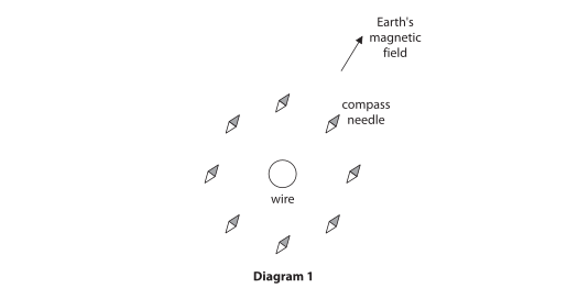
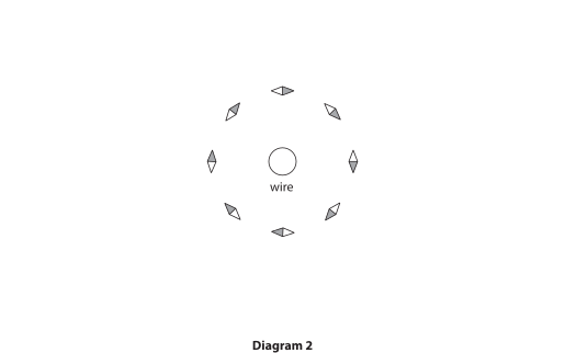
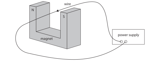
Diagram 3 shows the wire placed in a uniform magnetic field.
The current is now switched on.
Draw an arrow to show the direction of the force on the wire. Diagram 3: a straight wire connected to a power supply placed between the poles of a magnet labelled N and S, producing a uniform magnetic field across the gap. Space is provided to indicate the direction of the force on the wire when current flows.
Final answer

Draw a vertical arrow pointing upwards to show the force on the wire.

N S wire force

Mark scheme points

  1. M1 The force arrow is vertical.
  2. M2 The force arrow points upwards.

Explanation

The arrow must show the force acting on the wire, not the direction of the current or magnetic field. Draw it at the wire and make its direction unambiguous.

  • Make the arrow exactly vertical.
  • Make the arrowhead point upwards.

Common mistakes

  • Drawing the force arrow horizontally or diagonally instead of vertically.
  • Drawing a vertical arrow pointing downwards.
  • Confusing the force direction with the direction of current in the wire.
  • Examiners reported that this part was completed very well by most candidates; secure both marks by making sure the arrow is clearly vertical and upwards.
Example 2: Reading an Experimental Diagram

Question 2

A student investigates how the strength of the magnetic field from a solenoid changes with distance from the end of the solenoid.

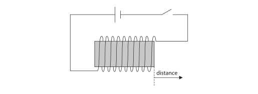
The diagram shows the solenoid connected to a power supply.

Diagram of a solenoid connected in a circuit to a power supply and switch; distance is measured from the end of the solenoid along its axis.

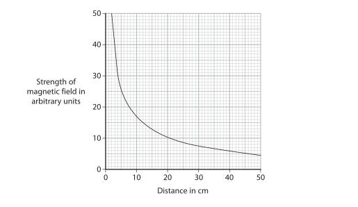
The graph shows the results of the student’s investigation.

Graph of strength of magnetic field (arbitrary units) against distance in cm from the end of a solenoid, from 0 to 50 cm; the curve decreases steeply at first then more gradually.

The student suggests that the relationship linking the strength of the magnetic field and the distance from the end of the solenoid is

strength of magnetic field × (distance)3

= constant

Use readings from the graph to deduce whether the results of the student’s investigation support this relationship.


Final answer

At distance = 10 cm, magnetic field strength = 17:
17 × 103 = 17 000

At distance = 50 cm, magnetic field strength = 4:
4 × 503 = 500 000

The constants are different, so the results do not support the suggested relationship.

Mark scheme points

  1. M1 Select two pairs of readings from the graph, such as 10 cm and 17, and 50 cm and 4.
  2. M2 Substitute the first pair into magnetic field strength × distance3 and calculate a constant: 17 × 103 = 17 000.
  3. M3 Use a different pair correctly to calculate another constant: 4 × 503 = 500 000.
  4. M4 State that the constants are different, so the results do not agree with the suggested relationship.

Explanation

For the proposed relationship to be supported, the value of magnetic field strength × distance3 must be constant for every pair of readings.

Read two points from the graph and calculate this product for each point. Using the readings at 10 cm and 50 cm gives 17 000 and 500 000 respectively. These values are not equal, so the product is not constant. Therefore, the investigation does not support the proposed relationship.

Common mistakes

  • Do not compare magnetic field strengths alone; calculate magnetic field strength × distance3.
  • Use the distance cubed, not just the distance or distance squared.
  • Use two different graph readings and show both substitutions clearly.
  • A conclusion is required: different constants mean that the suggested relationship is not supported.
  • Examiners noted that candidates who scored well used graph readings as directed, substituted them into the relationship, and compared the resulting constants.

Practise Electromagnetism questions

Build a focused practice set from this part of the Edexcel IGCSE Physics syllabus.